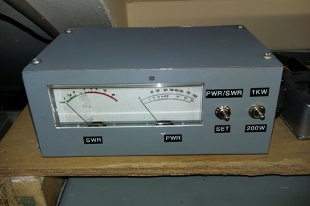
This HF swr meter gives good performance across all of the HF band and is capable of passing over 1000W without issue. It is useable at powers as little as 10W.
A low power alternative ( up to 200W ) is also shown as this uses common FT50-43 ferrite rings for the coupling transformers. The high power version uses FT114-43 ferrite rings which can be purchased on Ebay at a cost of £6.00 for six rings at the time of writing. The circuit is simple and uses a Stockton SWR bridge, as used in several a well known Ham transceivers and ATU's, the time consuming part was experimenting with different transformer cores / turns to give best results. As you can see, no expense has been spared in the building of this unit - I donned the black armband and bought some ferrite cores.
The circuit is built on a small PCB, other methods would also be suitable ( perforated board etc. ). The two transformers should be mounted at 90 degrees to each other to avoid any stray cross coupling. The two diodes should be matched to within ten percent of each other ( Vf ), the diode test function on a DMM can do this.
Two redundant VU meters are used here with their scales reprinted using a image manipulated by Photoshop, any meters with a suitable FSD will be ok. Calibration was done with a Bird meter for comparison, however a diode probe can be used with a DVM using the formula P = Vrms X Vrms / Rload. In other words power in Watts into a 50 Ohm dummy load = Vrms squared divided by 50. The values for resistors R1 and R2 were found by initially using a 100K trimmer and adjusting for correct power reading during calibration, these were then substituted by fixed resistors.
Barry Zarucki M0DGQ
HOME